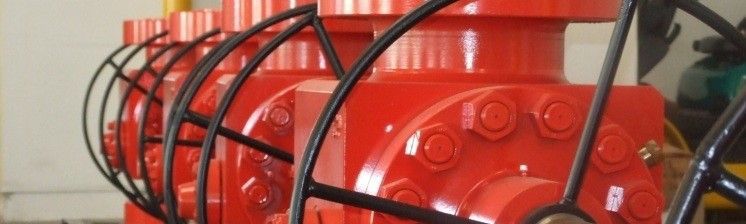
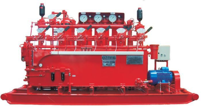
The accumulator unit module produce, store and deliver hydraulic energy under the form of fluid under controlled pressure to the connection pipes/hoses sledge assembly.
The accumulator unit module is mounted at approximate 80-100 feet from the well bore, outside the explosion hazard zone. Accumulators are pressure vessels used to store hydraulic energy by compressing a blanked of nitrogen over an oil filled area. The accumulators are cylindrical type, with a stainless steel float that partially separates the oil from the nitrogen which assure a long live compare with membrane or piston with rubber gasket versions.
The reservoir has a rectangular shape, contain baffle, fill and drain ports and stores the hydraulic fluid at the atmospheric pressure.
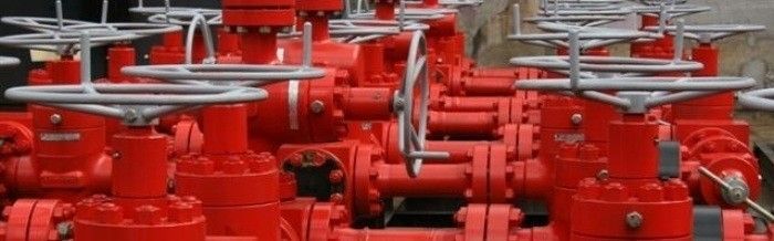
Highly sensitive hydro-pneumatic or electrical, self-relieving regulators efficiently control hydraulic pressure while drill pipe and tool joints on being stripped. The accumulator unit module has warning lamps and alarm, to indicate low accumulator pressure, low air pressure, low hydraulic fluid level.
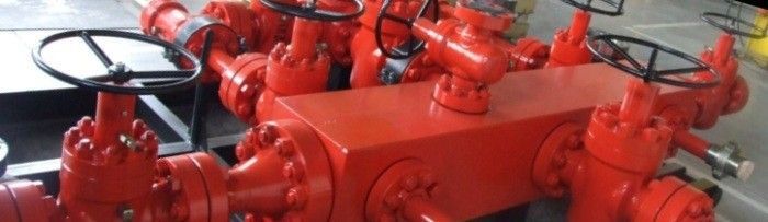
Accumulator unit module is connected to the preventers by a system of pipes and fire tested hoses (standard-flexible hoses 20 feet long at each end combine with steel pipes install on racks, total length minim 100 feet).On request other configurations available. Connection between accumulator unit module and driller remote control panel is made in the pneumatic version with a multiple pneumatic remote control lines encased in polyurethane sheeting and fitted with quick change junction's bots for easy attachment. Electrical version use a multiple wire cable with ends quick connectors.
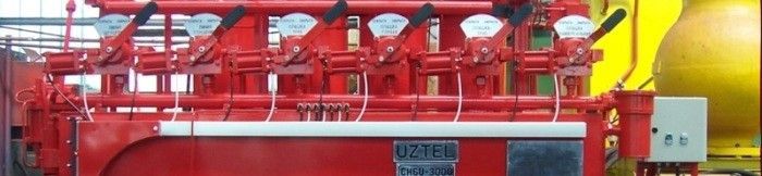
The air or electrical remote control panel has a memory system which indicates the last position of stack function.
Air or electrical remote control panels provide control and pressure monitoring of the BOP Control System. Air or electrical remote control panels can be provided in a wide variety of size, styles and configurations to meet specific space and operational criteria. All air or electrical remote control panels contain a master control valve or a master button which must be operated simultaneously with the selected function to initiate the operation.
UZTEL is able to offer a wide range of equipments which satisfys the technical and economical requirements of each client.
| Item | Features | MODEL | ||||||
| MD 03/MD03E | MD 05/MD05E | MD 08/MD08E | MD 10/MD10E | MD 16/MD16E | MD WO4 | |||
| 1 | Maxim working pressure | 210bar (3000 psi) | ||||||
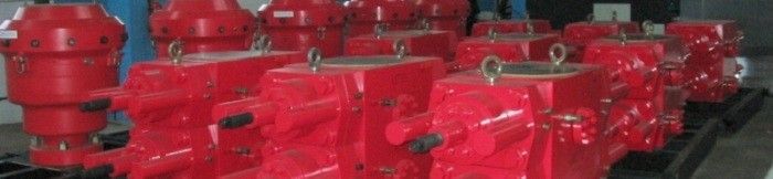
| 2 | Pumps | main | electrically driven | |||||
| secondary | pneumatically operated | |||||||
| 3 |
Hydropneumaticaccumulator modul volume |
4x80=320 litres 4x21.13=84.5gal |
6x80=480 litres 6x21.13=128.8gal |
8x80=640 litres 8x21.13=169gal |
10x80=800 litres 10x21.13=211.3gal |
16x80=1280 litres 16x21.13=338.1gal |
4x80=320 litres 4x21.13=84.5gal |
|
| 4 |
Fluid volume used for 70 to 210 bar/1000 to 3000 psi |
4x40=160 litres 4x10.57=42.3gal |
6x40=240 litres 6x10.57=63.4gal |
8x40=320 litres 8x10.57=84.6gal |
10x40=400 litres 10x10.57=105.7gal |
16x40=640 litres 16x10.57=169.1gal |
4x40=160 litres 4x10.57=42.3gal |
|
| 5 | Safety relief valve | 1/2in x 220 bar (3140 psi) | ||||||
| 6 | Tank volume |
650 litres 171.7 gal |
1000 litres 264.2 gal |
1000 litres 264.2 gal |
1000 litres 264.2 gal |
1400 litres 370.0 gal |
650 litres 171.7 gal |
|
| 7 | Pump flow | main | 17.4 litres/min at 1000 rot/min | 28 litres/min at 1000 rot/min | 28 litres/min at 1000 rot/min | 40 litres/min at 1000 rot/min | 40 litres/min at 1000 rot/min | 17.4 litres/min at 1000 rot/min |
| secondary | variable | |||||||
| 8 | Electromotive power for triplex pump actuating |
11 kw 1450 rot/min |
18.5 kw 1450 rot/min |
18.5 kw 1450 rot/min |
22 kw 1000 rot/min |
22 kw 1000 rot/min |
11 kw 1450 rot/min |
|
| 9 | Trapezoidal belt type | B 17x11- 1626 | B 17x11- 1850 | B 17x11- 1850 | SPA 12.5x10-1765 | SPA 12.5x10-1765 | B 17x11- 1626 | |
| 10 |
Mains frequency / supply voltage |
50Hz /380V 60Hz / 460V |
50Hz /380V 60Hz / 460V |
50Hz /380V
60Hz / 460V |
50Hz /380V
60Hz / 460V |
50Hz /380V
60Hz / 460V |
50Hz /380V
60Hz / 460V |
|
| 11 | Auxiliary hydro-pneumatic pumps number | 1 | 2 | 2 | 2 | 3 | 1 | |
| 12 | Hydro-pneumatic pumps ratio (hydraulic/pneumatic pressure ratio) | 60:1 | ||||||
| 13 | Standard number of station fluid control | 6 | ||||||
| 14 | Size of houses / pipes | 1 in | ||||||
| 15 | Actuating distribuitors type | 4 way x 3 positions, 1 in x 210 bar/3000 psi (selector) | ||||||
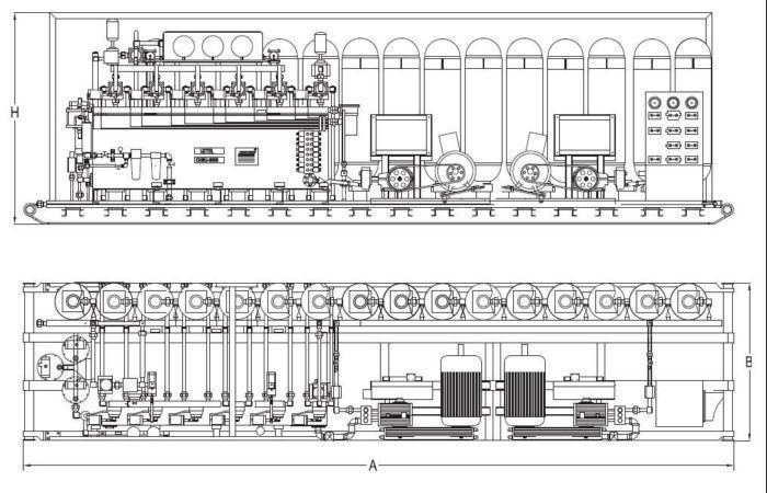
| 16 |
Overal dimensions (mm/in) Lenght (A): Width (B): Height (H): |
4020/158.27 1140/44.88 2060/81.10 |
4225/166.34 1540/60.63 2060/81.10 |
4345/171.06 1540/60.63 2060/81.10 |
4785/188.38 1540/60.63 2060/81.10 |
5560/218.9 1800/70.9 2060/81.10 |
3475/136.82 1200/47.25 2060/81.10 |
|
| 17 | Net weight (kg / lbs) | 3500/7716 | 4500/9921 | 5950/13117 | 6250/13779 | 8650/19070 | 3000/6614 | |
| Note: All dates are just for information only. Please contact UZTEL for more informations | ||||||||
")
")
")